Note: It may be helpful to print out these instructions before you start to replace the transfer unit.
Part I: Remove old transfer unit and unpack the new one.
| Figure | Step |
|---|---|
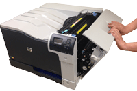
Figure 1.1: Open the right door
|
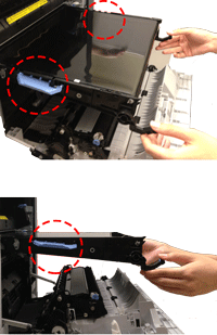
1.1. Open the right door.
CAUTION: Do not touch the shiny black surface of the belt on the top of the transfer unit, or place anything on it. This may damage the transfer unit and cause print quality problems. |
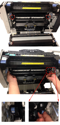
Figure 1.2: Grasp the front handles
|
1.2. Grasp the handles on the front of the transfer unit, as shown in the callout of Figure 2. |
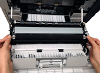
Figure 1.3: Pull the transfer unit
|
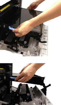
1.3. Pull the ITB out of the product until two large handles expand along the right and left sides of the ITB, as showing in Firuge 3 .
CAUTION: Never pull out the transfer unit uptilt. As you pull the transfer unit part way out, be careful to maintain its alignment with the slot that holds it in the printer. The transfer unit should come out easily. |
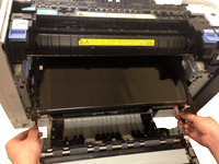
Figure 1.4: Switch your hands
|
1.4. Grasp the large handles on the ITB, continue to slide the ITB out of the product until it stops, as shown in Figure 1.4.
CAUTION: Do not touch the shiny black surface of the belt on the top of the transfer unit, or place anything on it. This may damage the transfer unit and cause print quality problems. |
Figure 1.5: Remove the transfer unit
|
1.5. Slightly rotate the ITB up, and gently finish pulling the transfer unit out of the printer. CAUTION: The transfer unit is a sensitive component. Be careful when handling the transfer unit, so that it is not damaged. |
Figure 1.6: Put the transfer unit on a clean surface
|
1.6. Put the transfer unit on a flat clean surface, in a safe and protected location. CAUTION: Do not touch the shiny black surface of the belt on the top of the transfer unit, or place anything on it. This may damage the transfer unit and cause print quality problems. |
Part II: Install new transfer unit.
| Figure | Step |
|---|---|
Figure 2.1: Grasp the large blue handles and align the transfer unit with its slot
|
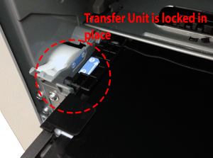
2.1. Grasp the transfer unit at the locations of large blue handles on both sides of the transfer unit, as shown in Figure 1. Align the transfer unit with its slot. CAUTION: Only push on the side handles of the transfer unit as indicated. Do not touch the shiny black surface of the belt on the top of the transfer unit, or place anything on it. This may damage the transfer unit and cause print quality problems. |
Figure 2.2: Lock the transfer unit
|
2.2. Gently push it a little bit into the slot until the transfer unit can hold itself. It should slide in easily. CAUTION: Make sure the transfer unit is locked and holds itself.
|
Figure 2.3: Switch your hands
|
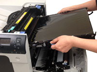
2.3. Switch your hands to the blue handles as shown in Firugre 2.3. CAUTION: Only touch the handles on the front of the transfer unit as indicated. Do not touch the shiny black surface of the belt on the top or front of the transfer unit, or place anything on it. This may damage the transfer unit and cause print quality problems. |
Figure 2.4: Insert the transfer unit
|
2.4. Gently finish inserting the transfer unit while maintaining its alignment with the slot in the printer, until it clicks into place. It should slide in easily. CAUTION: Only touch the handles on the front of the transfer unit as indicated. Do not touch the shiny black surface of the belt on the top or front of the transfer unit, or place anything on it. This may damage the transfer unit and cause print quality problems. |
Part III: Remove old secondary transfer unit and uppack the new one.
| Figure | Step |
|---|---|
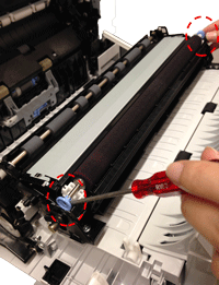
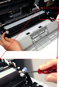
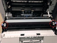
Figure 3.1: Release the roller shaft
|
3.1. Use a small flat-blade screwdriver to carefully release the roller shaft from the collars, as shown in Figure 3.1.
|
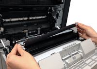
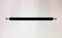
Figure 3.2: Remove the secondary transfer roller.
|
3.2. Grasp the two ends of the secondary transfer roller, and carefully take it out of the printer, as shown in Figure 3.2. |
Figure 3.3: Put the secondary transfer roller on a clean surface
|
3.3. Put the secondary transfer roller on a flat clean surface, in a safe and protected location. CAUTION: Do not touch the spongy roller surface of the secondary transfer roller. Skin oils on the roller can cause image quality problems. |
Part IV: Install new secondary transfer unit.
| Figure | Step |
|---|---|
Figure 4.1: Align the secondary transfer roller with its slot
|
4.1. Align the secondary transfer roller with its slot, as shown in Figure 4.1. |
Figure 4.2: Push the two sides in
|
4.2. Gentally press the two sides in until they click into place, as shown in Figure 2.2. |
Figure 4.3: Close the right door
|
4.3. Lift up the right door until it clicks into place. This will also lift the secondary transfer roller assembly to the position in which it is fully engaged. |
![]()
Please let HP know if this helped you to resolve your issue, and help HP improve service.
![]()